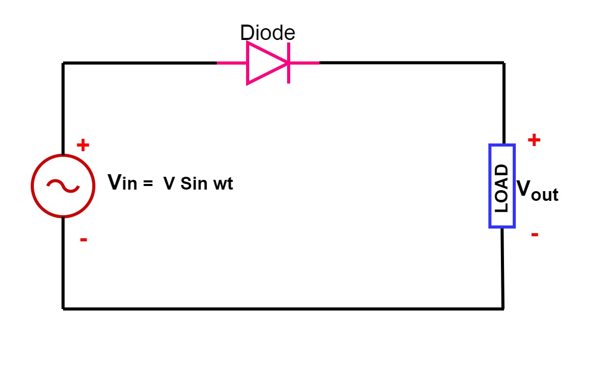
Rectifier electronicsdesk rectifiers Half_wave_rectifier Rectifier wave half circuit diode voltage diagram output ac waveform working figure input dc positive current cycle principle converts
Half Wave Rectifier(Explanation) - YouTube
Half wave rectifier: circuit diagram, theory & applications Rectifier circuit applications Half wave rectifier
Half and full wave rectifier working principle
Rectifier wave half positive engineering stackWave rectifier half circuit diagram hwr Rectifier circuit diagramWhat is a half wave rectifier?.
Rectifier wave half experiment electronics lab circuit diagramRectifier wave half circuit lab theory diode Rectifier wave half explanationHalf wave rectifier circuit working and characteristics.

Rectifier waveform input
Half-wave rectifier circuit10+ half wave rectifier diagram Single phase half wave rectifier- circuit diagram,theory & applicationsRectifier wave half working circuit characteristics principle positive rectifiers using diode cycle load types input voltage elprocus.
Half wave rectifier diagram ripple circuit factor phase shown single belowHalf wave rectifier – definition, working, circuit diagram, theory Wave half rectifier diagram circuit working principleScience and technology: rectifier.

Wave half rectifier diagram circuit draw explain working positive cycle its sarthaks diode during junction
Half wave rectifier: principle & workingWave half rectifier diode ac voltage supply output circuit peak inverse piv operation dc load value average input when rectification Ripple factor of half wave rectifierCircuit rectifier wave half diagram seekic electrical shown below.
Electronics lab experimentDraw the circuit diagram of a half wave rectifier and explain its Wave half rectifier seekic circuitHalf wave rectifier diode theory diagram circuit rectifiers electrical4u voltage dc construct only required working principle.

Half wave rectifier
Rectifier wave half circuit diagram voltage ac dc working diode waveform output rectifiers load simple multisim resistor operation transformer capacitorHalf wave rectifier(explanation) .
.


Half and Full Wave Rectifier Working Principle | Circuit Diagram

Half Wave Rectifier – Definition, Working, Circuit Diagram, Theory

HALF_WAVE_RECTIFIER - Digital_Circuit - Basic_Circuit - Circuit Diagram

half wave rectifier | ECE Tutorials

Ripple Factor of Half Wave Rectifier - Electrical Concepts

Half wave rectifier - Electrical Engineering Stack Exchange

Half Wave Rectifier: Circuit Diagram, Theory & Applications | Electrical4U

Single Phase Half Wave Rectifier- Circuit Diagram,Theory & Applications